The complete assembly instructions are here to help you decide if you’re up to the DIY portion of the project.
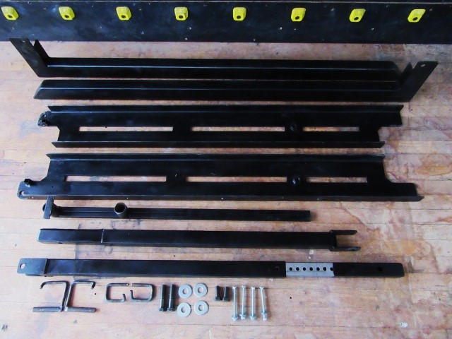
What you get!
Feet that attach to your 8.5″ kick board
Channels that attach to your 8’x8′ wall
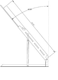
Telescoping struts that allow you to adjust the angle from 40 to 25 degrees in 13 steps.
Spanner bar, for changing the angle of the wall.
All custom and standard hardware for all metal to metal connections.
Measure your ceiling height!
The 8’x 8′ board is most easily built flat on the floor, plywood side up, and then flipped for assembly. An 8′ or lower ceiling height changes the orientation and order of assembly.
Ceilings 97″ or higher
With ceilings this high the easiest way is to flip the board ‘left for right’ with the side channels in place before the flip.
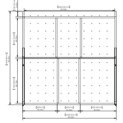
*The frame dimensions for the side members are sized so that the top horizontal member ends up just below the top row of T-nuts on a Mini Moonboard. This is done to create clearance for the frame so that the plywood can be raised all the way to the ceiling. If you are using a different T-nut layout you may want to adjust this length accordingly.
Because the LED wires are too short to hop the horizontal 2×6 the boards using LEDs are framed differently.
Cut list;
(2) 2×6″ 90.5″
(3) 2×6″ 93″
(2) 2×4″ 45.75″
(2) 2×4″ 40.25″
Two of the 2x4s can be salvaged out of the crate material.
Kickboard
You will also need (2) 96″ 2x4s and some short blocks. The blocks can be salvaged out of the crating material.
Tools
2 Saw horses. (Home Depot has assembled saw horses)
Circular saw and small hand saw (just about any type of small hand saw will do)
3/16″ and 5/16″ twist drills and drill motor. 1 1/2″ paddle bit
Flat or half round wood rasp
Tape measure (a metric tape measure is very handy for doing the layout for Moon T-nuts)
Vice Grip and 4″ bar clamp
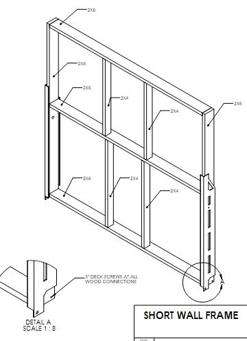
Note that the 2×4 braces are positioned to fit the Mini Moonboard and can be moved left or right to fit your custom T-nut layout. The braces for the top and bottom panels do not need to be stacked and can be in different bays. Actually I have found that more offset than shown makes it easier to get the screws in.
If you’re going to paint the plywood I would recommend doing that as a first step so that it has maximum drying time before mounting your holds. Drill and install T-nuts.
Frame the 96″x 90.5″wall(see caveat above cut list) (do not frame the kick wall at this time)( a handy tip is to drill though the outside member with a 3/16 bit to simplify alignment of the frame members before installing the 2 3/4″ screws) with the bottom of the frame adjacent to the final kick wall location. When mounting the plywood view the wall standing at the bottom to keep left and right sides straight in the case of an asymmetric T-nut layout like the Moonboard. Be certain that the bottom corners of the frame are truly 90 degrees by making sure that the bottom sheet of plywood lines up flush with the frame on three sides and especially flush at the bottom two corners.
Once the plywood is in place you are ready to fit the side channels. Put the wall up on blocks to get it off the floor. Put the channels in position with the long flange, with the drilled holes, tight against the plywood. The steel frame members are labeled left and right as a climber would see them when facing the plywood Near the ends of the channels there are short pieces of 3/4″ square tubing welded on to act as bottom stops to locate the channels. With these stops slid up to the framing, mark location of the 5/8″ threaded hole. Also mark where the end of the channel is on the plywood. Remove the channels and drill 1 1/2″ holes in the 2x6s to create clearance for the welded nut. The plywood needs to be chamfered to create clearance for the radius inside the steel channel. This chamfer is very easy to do with a rasp. The chamfer is really just breaking the corner a little bit and does not have to be pretty as it’s hidden by the channel. Verify that the channels fit flush on the wall and the bottom stop is in contact with the frame. Install deck screws in the counter sunk holes provided.
You are now ready to frame the kickboard.
96″ or 95″ ceilings
96″ or lower ceilings create the problem that though the wall is easiest to build plywood up on the floor, there will be no way to flip it into position for mounting it on the kick wall/ floor brace assembly.
One solution is to trim off an inch or more off of the top of the plywood. Notice that this does not change or reduce the climbing surface as this removed plywood is all well above the top row of holds. This reduced plywood height also allows the wall angle to be raised all the way to 25 degrees before hitting the ceiling. I recommend cutting the plywood so the the resulting wall ends up 1″ shorter than your ceiling height.
This shortened wall will flip ‘top for bottom’ before the channels are installed so the top of the frame should be adjacent to the ending location off the kick wall.
Frame the 96″x 90.5″ wall (do not frame the kick wall at this time) with the bottom of the frame adjacent to the final kick wall location. When mounting the plywood view the wall standing at the bottom to keep left and right sides straight in the case of an asymmetric T-nut layout like the Moonboard. Be certain that the bottom corners of the frame are truly 90 degrees by making sure that the bottom sheet of plywood lines up flush with the frame on three sides and especially the bottom corners.
Once the plywood is in place you are ready to fit the side channels. The steel frame members are labeled left and right as a climber would see them when facing the plywood. Put the wall up on blocks to get it off the floor. Place the channels in position with the long flange, with the drilled holes, lying tight on the plywood. Near the ends of the channels there are short pieces of 3/4″ square tubing welded on to act as bottom stops to locate the channels. With these stops slid up to the framing, mark location of the 5/8″ threaded hole. Also mark where the end of the channel is on the plywood. Remove the channels and drill 1 1/2″ holes in the 2x6s to create clearance for the welded nut. The plywood needs to be chamfered to create clearance for the radius inside the steel channel. This chamfer is very easy to do with a rasp . The chamfer is really just breaking the corner a bit and does not have to be pretty as it’s hidden by the channel. A rasp work well for this. Verify that the channels fit flush on the wall and the bottom stop is in contact with the frame.You will need to flip the board before you attach the channels to the wall. With the plywood side down block the wall to get it off the floor. Put the channels in place and move your blocks to hold the channel flange tight against the plywood. Verify that the stop is against the bottom of the frame and install 1 5/8″ deck screws in the counter sunk holes provided on the sides of the wall. The screws on the plywood face can be installed after the wall is in place at 40 degrees.
You can now verify the measurement that you need to frame the kickboard.
95″ to 91.5″ ceilings
For ceilings below 91.5″ consult Bluesman Boards
In order to flip the wall with ceilings this low, the wall can be constructed with the top panel being attached last after the frame is assembled and at 40 degrees. Build the 96″x90.5″ frame and attach the lower panel as normal using the lower panel to insure that the bottom corners of the frame are square.
Two 1 7/8″x 10 1/4″ spacers can be cut from the top panel to fit under the channels.
Fasten the spacers to the 2×6 wood frame with the top panel lying loose in place to insure that you are leaving plenty of clearance for it to be permanently installed later. With the wall blocked up off the floor fit, but do not install, the channels as in the ’96” or 95″ ceilings’ instructions. Flip the frame and lower panel. and install the channels. If you ceiling is lower than the height of the frame you may be able to utilize spaces between exposed ceiling joists to accomplish the flip. Follow the ’96” or 95″ Ceilings’ instructions until the board is at 40 degrees and install the top panel.
LEDs
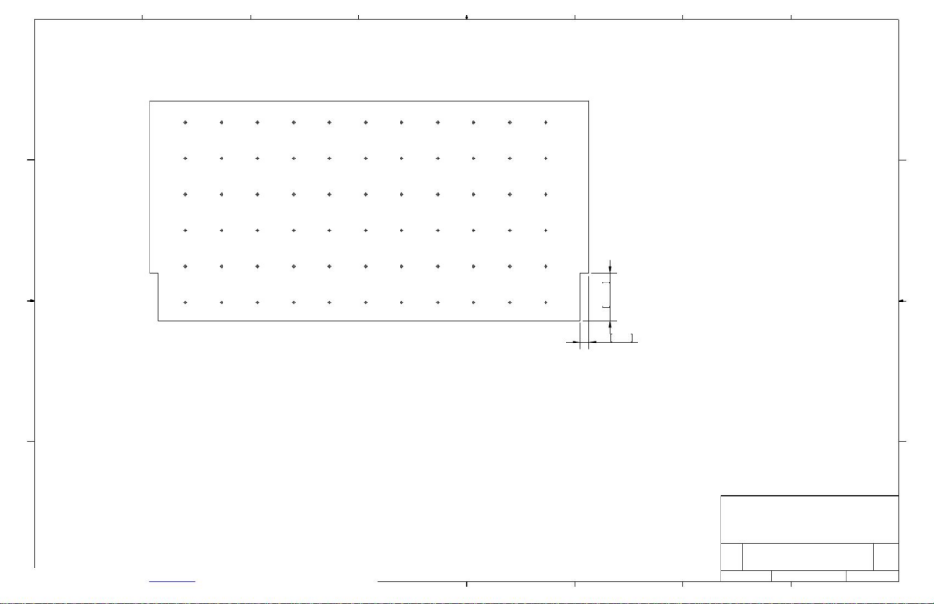
The wiring of the LEDs is long enough to easily hop the 2×4 braces, but not the horizontal 2×6 member. Because of this you will need to drill a row of 1-1/2″holes (11) down the center of the 2×6 adjacent to each vertical row of T-nuts. The first hole will be 16cm from the end and then on 20cm centers after that. Don’t forget the asymmetric layout when orienting this framing member.
The horizontal framing member also interferes with the LED holes for row 7. From the plywood side and after the plywood is installed onto the wood frame. Using a 1/2″ twist drill. Insert the drill bit into the existing hole and angle the bit up about 45 degrees towards the top of the wall. Drill to create clearance for the LEDs. The bottom plate of the wood frame also interferes with the row 1 LED holes. These are best relocated after the row 1 holds are in place in order to locate them in sensible positions. Note that on the 2020 board row one is not even populated and the 2025 set only has 8 holds on the bottom row.
Kickboard
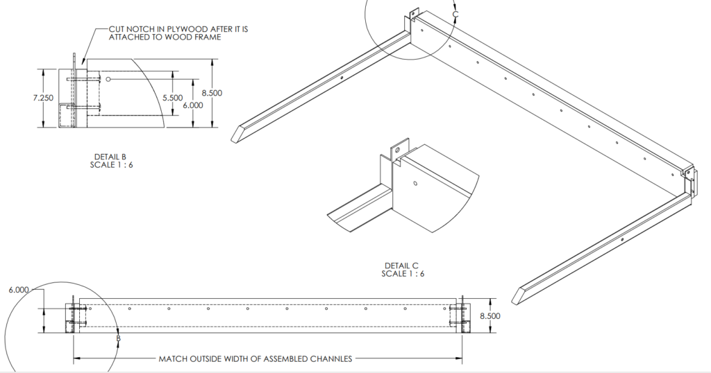
The kickboard plywood panel measures 96″ x 8 1/2″ and does not have to be in one piece. If you are using 48″x8.5″ panels for your kickboard you need to insure that the top of the panels result in a straight line. There is a minimized gap at the apex of the kickboard/main wall connection and a kickboard frame that is not straight will effect the clearance at the apex
If you’re building a Mini Moonboard the T-nuts will be 6″ up from the bottom to put them the spec distance from the apex. Side to side spacing is on Moon’s site.
Measure the outside to outside dimension of the channels at the pivot ‘ears’ at the bottom of the wall. This is typically 96 3/8″ but could be a little different on your wall. Your measurement will be the dimension of your kickboard frame. For clarity the following directions will assume that your measurement is 96 3/8″ The frame can be 2x4s throughout and the long members of the frame will be your measurement less 3″ to allow for the spacer blocks. Frame a 93 3/8″ x 8 1/2″ rectangle and add a 7 1/4″ block to each side. Screw on a 96″ x 8 1/2″ piece of plywood and use the plywood to keep the frame square. The plywood does not have to be one piece and will normally be a little short. This cause no problems, just leave a 3/16″ gap on each side. Be sure to get a couple of screws into the short blocks on the ends as these blocks are what keep the floor braces attached and plumb. Use a hand saw to cut out the 1 1/4″ squares on each side.
Once the kickboard panel is complete you can attach it to the floor braces. Assemble the floor braces and kickboard as shown, making sure that the bottoms of all three pieces are in the same plane. It’s probably easiest to shim everything level as you’re probably going to want it level in the end anyway. Clamp the floor brace to the kickboard with the plywood face flush with the angle face of the floor braces. Drill though the holes in the angle and the two end blocks of the kickboard and install the supplied 5/16″ carriage bolts with the carriage heads into the wood and the washers and nuts on the steel sides. Leave the 5/16″ carriage bolts loose at this time.
Assembling the wall to the kickboard
Use saw horses or other to support the wall at approximately the angle shown and close to the balance point. The higher the angle the more clearance you will have to make the connection to the floor braces. Align the holes with the channels inside of the floor braces using one of the 5/8″ gravity pins as an alignment tool. Leaving the 5/16′ carriage bolts loose helps with aligning everything. A vicegrip clamping the two flanges together will be helpful in installing the 1 1/2″x5/8″ bolts without damaging the threads. The 5/8″ nuts with the tails go in the 1 1/4″ squares that you have cut out, tails toward the rear. The tails are so that you don’t need a second 15/16″ wrench to tighten the hinge bolts after setting the angle. They also allow the whole climbing wall to be slid back against the room wall without worrying about clearance for the second wrench. Install the Grade 5-5/8″ x 1 1/2″ bolts as far as you can with the washer on the outside before engaging the nut. This is to minimize damage to the threads. Leave the bolts slightly loose at this time so that the connection can pivot.
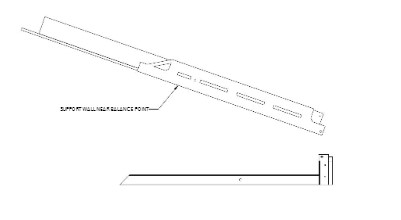
Telescoping Support Struts
The male portion (top)of the telescoping struts are installed with the shimmed side against the channels. They are marked climbers left and right, the female portions are wired to the male portions to keep the orientation correct and may or may not be interchangeable. Install the 3/8″ gravity pins with the telescopes fully collapsed. With the struts loosely bolted to the channels you are ready to lift the wall to the 40 degree position. I have done this by myself, but I recommend at least two people. As you are lifting the wall the bottom of the struts will slide towards the floor braces. When you can position the saddles onto the floor braces and continue lifting. At some point as the struts approach vertical they will start supporting the wall. When they are all the way vertical you can relax and install the 5/8″ gravity pins in the floor braces. If you are going to use the board at 40 degrees just snug the hinge bolts and the bolts at the top of the struts and install your holds. Snug bolts make a much stronger connection, but overly tight bolts will prematurely wear the threads if the bolts are loosened and tightened often.
Changing the angle
This is easily done with one person using the spanner bar*. Loosen the four Grade 5 5/8″ bolts. Remove the gravity pins and lift one side a little bit. Try to keep the amount of exposed telescope close to even to keep the telescopes from binding up. I’ve included two extra 3/8″ pins for each side that can be placed in holes above the female tubes for convenience or safety, though the strut will always be in place so the wall can not come down lower than the 40 degree position in the case of a mishap. When you have reached the desired angle snug the four 5/8″ bolts and you’re ready to climb. Note that there is nothing wrong with using the gravity pins in the holes above the female tubes for angles that fall between the normal positions and the holes are positioned to split the difference.
* After assembling a wall using Moon panels, which are significantly heavier than the plywood that I used on my wall, I could still change the angle alone but it became obvious that “easily done with one person” would be relative to the weight of the wall and the strength of the person. At over 73 years old I had assumed that if I had no problems changing the angle alone, no one else would. In retrospect, I could easily imagine a spray wall covered with heavy holds that would be too heavy for me to handle alone. I would suggest a second person pushing on the top of the wall with a padded 2×4 to ease the situation in this case.